Home
/ 555 Timer Ic Schematic Diagram : IC 555 Timer Working: Pin Diagram, Specifications & Features : The 555 timer ic is a very cheap, popular and useful precision timing device which can act as either a simple timer to generate single pulses or long time delays, or as a relaxation oscillator producing a string of stabilised waveforms of varying duty cycles from 50 to 100%.
555 Timer Ic Schematic Diagram : IC 555 Timer Working: Pin Diagram, Specifications & Features : The 555 timer ic is a very cheap, popular and useful precision timing device which can act as either a simple timer to generate single pulses or long time delays, or as a relaxation oscillator producing a string of stabilised waveforms of varying duty cycles from 50 to 100%.
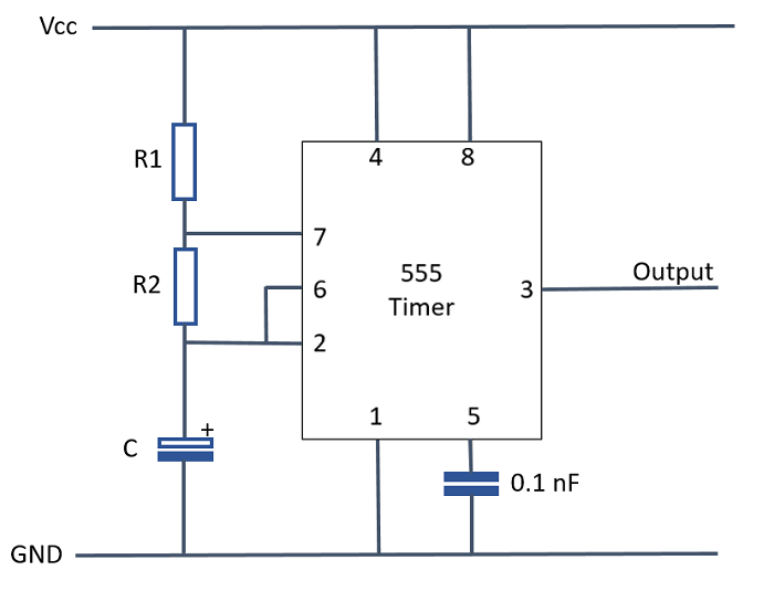
555 Timer Ic Schematic Diagram : IC 555 Timer Working: Pin Diagram, Specifications & Features : The 555 timer ic is a very cheap, popular and useful precision timing device which can act as either a simple timer to generate single pulses or long time delays, or as a relaxation oscillator producing a string of stabilised waveforms of varying duty cycles from 50 to 100%.. The 555 timer ic is an integrated circuit (chip) used in a variety of timer, delay, pulse generation, and oscillator applications. Jul 14, 2015 · we can use this property of 555 timer to create various timer circuits like 1 minute timer circuit, 5 minute timer circuit, 10 minute timer circuit, 15 minute timer circuit, etc. Resistive network consists of three equal resistors and acts as a voltage divider. All we need to change the value of resistor r1 and/or capacitor c1. It is similar to the previous circuit.
The 555 timer ic is an integrated circuit (chip) used in a variety of timer, delay, pulse generation, and oscillator applications. We need to set 555 timer in monostable mode to build timer. 555 timer helpers schematic the addition of a capacitor to the trigger will not work for short output pulses as there is also a short delay in the recovery of the trigger terminal voltage. Derivatives provide two or four timing circuits in one package. The second 555 timer helper will extend the timers output duration without having to use large values of r1 and/or c1.
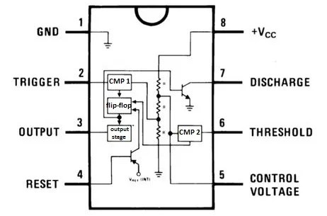
Introducing 555 Timer IC - Tutorial | Random Nerd Tutorials from i2.wp.com Since the application is built on cloud, it gives the convenience of mobility and portability. The block diagram of a 555 timer is shown in the above figure. All we need to change the value of resistor r1 and/or capacitor c1. It is similar to the previous circuit. The circuit using the ic lm3622 can be fed with voltages right from 5 to 24v depending upon the charging needs and the connected battery. The 555 timer ic is a very cheap, popular and useful precision timing device which can act as either a simple timer to generate single pulses or long time delays, or as a relaxation oscillator producing a string of stabilised waveforms of varying duty cycles from 50 to 100%. Another advantage that comes with a cloud application is cross device compatibility. May 23, 2021 · schematic diagram of dual dc regulator 15v using transistor and zener diode.
The block diagram of a 555 timer is shown in the above figure.
Another advantage that comes with a cloud application is cross device compatibility. It was commercialized in 1972 by signetics. 555 ic timer block diagram 555 ic timer block diagram. The second 555 timer helper will extend the timers output duration without having to use large values of r1 and/or c1. The circuit using the ic lm3622 can be fed with voltages right from 5 to 24v depending upon the charging needs and the connected battery. Nov 05, 2011 · they have over 70,000+ readily available schematic in their web database along with 15,000+ pspice libraries. Derivatives provide two or four timing circuits in one package. Resistive network consists of three equal resistors and acts as a voltage divider. The block diagram of a 555 timer is shown in the above figure. They consist of t1, d1, d2, d3, d4, c1, and c2. It is similar to the previous circuit. Lets list out free circuit diagram drawing softwares first. Since the application is built on cloud, it gives the convenience of mobility and portability.
Lets list out free circuit diagram drawing softwares first. It is similar to the previous circuit. 555 ic timer block diagram 555 ic timer block diagram. They consist of t1, d1, d2, d3, d4, c1, and c2. The block diagram of a 555 timer is shown in the above figure.
Electronic Projects from electronic-projects.50webs.com 555 ic timer block diagram 555 ic timer block diagram. The 555 timer ic is a very cheap, popular and useful precision timing device which can act as either a simple timer to generate single pulses or long time delays, or as a relaxation oscillator producing a string of stabilised waveforms of varying duty cycles from 50 to 100%. It is similar to the previous circuit. The circuit using the ic lm3622 can be fed with voltages right from 5 to 24v depending upon the charging needs and the connected battery. Lets list out free circuit diagram drawing softwares first. We need to set 555 timer in monostable mode to build timer. Since the application is built on cloud, it gives the convenience of mobility and portability. Nov 05, 2011 · they have over 70,000+ readily available schematic in their web database along with 15,000+ pspice libraries.
Resistive network consists of three equal resistors and acts as a voltage divider.
It is similar to the previous circuit. Since the application is built on cloud, it gives the convenience of mobility and portability. May 23, 2021 · schematic diagram of dual dc regulator 15v using transistor and zener diode. The circuit using the ic lm3622 can be fed with voltages right from 5 to 24v depending upon the charging needs and the connected battery. In monostable mode, the duration for. Jul 14, 2015 · we can use this property of 555 timer to create various timer circuits like 1 minute timer circuit, 5 minute timer circuit, 10 minute timer circuit, 15 minute timer circuit, etc. Resistive network consists of three equal resistors and acts as a voltage divider. These components are the unregulated supply section. Another advantage that comes with a cloud application is cross device compatibility. The block diagram of a 555 timer is shown in the above figure. 555 timer helpers schematic the addition of a capacitor to the trigger will not work for short output pulses as there is also a short delay in the recovery of the trigger terminal voltage. Nov 05, 2011 · they have over 70,000+ readily available schematic in their web database along with 15,000+ pspice libraries. It was commercialized in 1972 by signetics.
Nov 05, 2011 · they have over 70,000+ readily available schematic in their web database along with 15,000+ pspice libraries. Lets list out free circuit diagram drawing softwares first. The 555 timer ic is an integrated circuit (chip) used in a variety of timer, delay, pulse generation, and oscillator applications. We need to set 555 timer in monostable mode to build timer. The second 555 timer helper will extend the timers output duration without having to use large values of r1 and/or c1.
555 timer circuit diagrams | different modes of 555 timer from i2.wp.com Since the application is built on cloud, it gives the convenience of mobility and portability. The second 555 timer helper will extend the timers output duration without having to use large values of r1 and/or c1. The 555 timer ic is an integrated circuit (chip) used in a variety of timer, delay, pulse generation, and oscillator applications. The circuit using the ic lm3622 can be fed with voltages right from 5 to 24v depending upon the charging needs and the connected battery. All we need to change the value of resistor r1 and/or capacitor c1. The block diagram of a 555 timer is shown in the above figure. It is similar to the previous circuit. These components are the unregulated supply section.
Nov 05, 2011 · they have over 70,000+ readily available schematic in their web database along with 15,000+ pspice libraries.
The block diagram of a 555 timer is shown in the above figure. Lets list out free circuit diagram drawing softwares first. The circuit using the ic lm3622 can be fed with voltages right from 5 to 24v depending upon the charging needs and the connected battery. We need to set 555 timer in monostable mode to build timer. 555 ic timer block diagram 555 ic timer block diagram. These components are the unregulated supply section. May 23, 2021 · schematic diagram of dual dc regulator 15v using transistor and zener diode. It is similar to the previous circuit. They consist of t1, d1, d2, d3, d4, c1, and c2. The 555 timer ic is an integrated circuit (chip) used in a variety of timer, delay, pulse generation, and oscillator applications. The second 555 timer helper will extend the timers output duration without having to use large values of r1 and/or c1. Derivatives provide two or four timing circuits in one package. All we need to change the value of resistor r1 and/or capacitor c1.
These components are the unregulated supply section 555 timer schematic. Since the application is built on cloud, it gives the convenience of mobility and portability.
